
I have been introducing some of my math students to 3d modeling using the openSCAD software package. The openSCAD documentation is really good, but can be intimidating to new users. This is a summary of some of the basic shapes and functions that will get you started using openSCAD.
Contents
Show Your Axes
Cubes and Translation
Parameters
Spheres
Cylinders
Difference
Modules
Other openSCAD Features
Show Your Axes
Before you begin modeling, go to View>>Show Axes. This will make it easier to see where the parts of your model are being placed.

An empty openSCAD window, with axes shown.
Cubes and Translation
A “cube” in openSCAD simply refers to a rectangular prism. To make a simple cube:
cube(5);

A simple cube in openSCAD.
If this is your first time using openSCAD, there are a few things you should know about the interface:
- To see your shape once you have entered the code, go to View>>Compile (F5).
- To zoom in on the shape, click on the drawing window and go to Edit>>Zoom In (Ctrl-+).
- To zoom out on the shape, go to Edit>>Zoom Out (Ctrl–).
- To view the shape from different angles, click on the drawing window and move your pointer.
- To move the origin of your axes, right-click the drawing window and move your pointer.
You can center your cube on the xyz axes:
cube(5, center=true);

A simple cube in openSCAD, centered on the coordinate system.
You can create a “cube” with different side lengths, by giving three separate parameters inside square brackets. The numbers in brackets refer to the size of the cube in the x, y, and z directions respectively:
cube([2,2,5], center=true);

A “cube” in openSCAD actually refers to any rectangular prism.
To move a cube anywhere you want, we use openSCAD’s translate function. The values passed to the translate function move the cube in the x, y, and z directions respectively. The following code will move our code 2 units in the x-direction, 4 units in the y-direction, and 6 units in the z-direction:
translate([2,4,6]){
    cube([2,2,5], center=true);
}

A cube that has been moved 2 units in the x direction, 4 units in the y direction, and 6 units in the z direction.
You can pass negative values to translate. The following code will move the cube 6 units down, instead of up:
translate([2,4,-6]){
    cube([2,2,5], center=true);
}

Giving translate a negative number moves it in the opposite direction. For example, a negative z-value moves the object down.
Intermission: Make something!
At this point, it is probably good to create a model or two using nothing more than translated cubes. Sketch a simple shape using just cubes, and try to create your shape in openSCAD. You might make a tower with a door and two windows, a smiley face with a cube for a head, two eyes, and a mouth.
Parameters
You can play with openSCAD using just numbers, and things will work. But when you want to make adjustments to your models, you will probably find yourself adjusting a whole bunch of numbers. openSCAD addresses this by letting you define parameters. Let’s make a letter L, using just numbers:
// Simple letter L, with just numbers

// Vertical leg
translate([0,0,5]) {
	cube([2,2,10], center=true);
}

// Horizontal leg
translate([3,0,0]) {
	cube([8,2,2], center=true);
}

A letter L, using just numbers.
This works, but it is pretty hard to make revisions. If we want to change our model, we have to change several numbers. For example, if you want to change the cross-sectional size of the legs, you will have to change 4 numbers, and even then you still have to go back and fix the lengths to match the new cross-section:
// Simple letter L, with just numbers

// Vertical leg
translate([0,0,5]) {
	cube([4,4,10], center=true);
}

// Horizontal leg
translate([3,0,0]) {
	cube([8,4,4], center=true);
}

Changing the cross-section of the legs is not straightforward using just numbers.
Let’s see how this same model looks using parameters:
// Simple letter L, with just numbers

// Parameters
vertical_leg_length = 10;
cross_section_width = 0.2*vertical_leg_length;
horizontal_leg_length = 0.8*vertical_leg_length;

// Vertical leg
translate([0,0,vertical_leg_length/2]) {
	cube([cross_section_width, cross_section_width, vertical_leg_length], center=true);
}

// Horizontal leg
translate([horizontal_leg_length/2-cross_section_width/2,0,0]) {
	cube([horizontal_leg_length, cross_section_width, cross_section_width], center=true);
}
Working with parameters can require a little more thinking up front, but leads to a model that is much easier to refine later. In line 4, we define our core parameter, the length of the vertical leg of the letter L. In line 5, we define our cross-sectional width in terms of the vertical leg length. In line 6, we make the horizontal leg 80% of the length of the vertical leg.
In line 9, we move the vertical leg up half of its length, so it sits on the x-y plane. The numbers in line 14 take a little more thought. We move the horizontal leg to the right by half the length of the horizontal leg. But then we have to shift it back left by half of the cross-sectional width, to line up with the left edge of the vertical leg. If these numbers are confusing in the model you are creating, you can still use guess-and-check to work things out. Here is the model, which is identical to the one we just made:
A letter L, using parameters.
But now if we want to change the cross-sectional width, we just have to change one number:
// Simple letter L, with just numbers

// Parameters
vertical_leg_length = 10;
cross_section_width = 0.4*vertical_leg_length;
horizontal_leg_length = 0.8*vertical_leg_length;

// Vertical leg
translate([0,0,vertical_leg_length/2]) {
	cube([cross_section_width, cross_section_width, vertical_leg_length], center=true);
}

// Horizontal leg
translate([horizontal_leg_length/2-cross_section_width/2,0,0]) {
	cube([horizontal_leg_length, cross_section_width, cross_section_width], center=true);
}
Since we have defined all of the relationships in terms of the first parameter, everything adjusts itself for us:

With appropriate use of parameters, we can efficiently make changes to our model.
Now let’s look at the rest of the shapes you can use in openSCAD.
Spheres
A simple sphere can be defined in one line:
// A simple sphere

sphere(5);

A simple sphere.
We can control the resolution of the sphere with the special parameter “$fn”. This setting controls the number of edges that are used to create a curve in openSCAD. You can think of this setting as “the number of faces along the equator of the sphere”. If you set $fn very high, you will get a smooth sphere but openSCAD will take a long time to render your models. It is good practice to use a moderate number, such as 20 or 40, while working, and then use a high number such as 100 or 150 for rendering your final versions.
// A simple sphere

$fn = 50;

sphere(5);

A higher-resolution sphere, with 50 faces around the equator.
// A simple sphere

$fn = 150;

sphere(5);

A really high-resolution sphere, with 150 faces around the equator.
The value for $fn applies to all rounded shapes in your model. If you want to have different resolutions for individual spheres, you can place the $fn setting within the call to make an individual sphere:
// A simple sphere

sphere(5, $fn=200);
Cylinders
A cylinder takes two variables to define, and responds to the $fn variable just as a sphere does. A cylinder needs a radius and a height:
// A simple cylinder

$fn = 50;

cylinder(r=3, h=5);

A simple cylinder.
Like cubes, a cylinder is often easier to work with if it is centered first:
// A simple cylinder

$fn = 50;

cylinder(r=3, h=5, center=true);

Cylinders are often easier to work with if they are centered first.
Cylinders have a vertical orientation by default. If we want a cylinder to lie horizontally, we can use the rotate function. The rotate function, like translate, takes 3 arguments. We can choose to rotate an object about the x-axis, the y-axis, or the z-axis:
// A simple cylinder

$fn = 50;

rotate([0,90,0]) {
	cylinder(r=3, h=5, center=true);
}

A cylinder, rotated sideways about the y-axis.
If you want to move a horizontal cylinder, make sure to put the translate function around the rotate function:
// A simple cylinder

$fn = 50;

translate([0,0,5]) {
	rotate([0,90,0]) {
		cylinder(r=3, h=5, center=true);
	}
}

To move a horizontal cylinder, rotate it first and then move it.
You make a cone by creating a cylinder a different radius for each end:
// A simple cylinder

$fn = 50;

cylinder(r1=5, r2=2, h=10, center=true);

A cone is just a cylinder, with a different radius for each end.
Setting one radius to zero makes a perfect cone:
// A simple cylinder

$fn = 50;

cylinder(r1=5, r2=0, h=10, center=true);
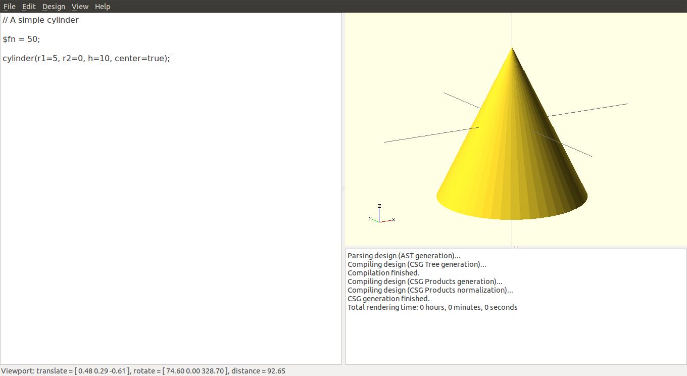
Setting one radius to zero makes a perfect cone.
Difference
Everything we have looked at so far can be used to build complex shapes by adding a bunch of smaller parts together. But sometimes we need to take pieces away. A good example of this is a ring; a ring is a cylinder, with a smaller cylinder removed from the middle. The difference function builds the first thing in the list, and removes everything else:
// A simple ring.

$fn = 50;

difference() {
	// This piece will be created:
	cylinder(r=10, h=5, center=true);

	// Everything else listed will be taken away:
	cylinder(r=8, h=6, center=true);
}

The difference function removes parts from your model.
It is very helpful to see what is being taken away from your model. Putting a pound sign in front of the pieces that are taken away makes them visible:
// A simple ring.

$fn = 50;

difference() {
	// This piece will be created:
	cylinder(r=10, h=5, center=true);

	// Everything else listed will be taken away:
	#cylinder(r=8, h=6, center=true);
}

The pound symbol lets us see what is being taken away.
The piece that is being taken away must be slightly larger in one dimension than the piece it is being subtracted from. For example, this is what happens if the cylinder removed from the middle has the same height as the outer cylinder:
// A simple ring.

$fn = 50;

difference() {
	// This piece will be created:
	cylinder(r=10, h=5, center=true);

	// Everything else listed will be taken away:
	cylinder(r=8, h=5, center=true);
}

If the inner cylinder is the same height as the outer cylinder, there is a zero-thickness “skin” on the ring.
There is a zero overlap between the outer and inner cylinders, which creates a “skin” of thickness 0. This is a bad thing in modeling, and will result in errors when trying to render or upload to a 3d printer. Using parameters demonstrates a good approach to this issue:
// A simple ring.

$fn = 50;

// Parameters
inner_radius = 8;
thickness = 2;
outer_radius = inner_radius + thickness;
height = 5;
padding = 0.1;

difference() {
	// This piece will be created:
	cylinder(r=outer_radius, h=height, center=true);

	// Everything else listed will be taken away:
	#cylinder(r=inner_radius, h=height+padding, center=true);
}

A simple ring, using parameters.
If you want to build up a few things before removing some parts, you can use the union function:
// A ring with a lip at the top

$fn = 50;

// Parameters
inner_radius = 8;
thickness = 2;
outer_radius = inner_radius + thickness;
lip_radius = outer_radius + thickness;
lip_height = thickness/2;
height = 5;
padding = 0.1;

difference() {

	// These pieces will be created:
	union() {
		// main body of ring
		cylinder(r=outer_radius, h=height, center=true);

		// lip at top of ring
		translate([0,0,height/2+lip_height/2]) {
			cylinder(r=lip_radius, h=lip_height, center=true);
		}

	}

	// Everything else listed will be taken away:
	#cylinder(r=inner_radius, h=height+2*lip_height+padding, center=true);
}

A ring with a lip.
This may seem to get complicated quickly, if you are used to a mouse-driven modeling program. But it is quite powerful to be able to write down an exact recipe for your models. We can quickly get into an efficient process of creating a model, and then making very precise refinements to our model. This approach certainly works better for some models than others.
Modules
Modules are a powerful feature of openSCAD. Once we have created a shape we like, we can give it a name. From that point on, making that shape is as simple as using the name we have given it. Let’s wrap our ring in a module:
// A simple ring.

$fn = 50;

// This line tells openSCAD to find the instructions for how to make a ring,
//  and then make the ring
ring();

// Instructions for how to make a ring
module ring() {

	// Parameters
	inner_radius = 8;
	thickness = 2;
	outer_radius = inner_radius + thickness;
	height = 5;
	padding = 0.1;

	difference() {
		// This piece will be created:
		cylinder(r=outer_radius, h=height, center=true);

		// Everything else listed will be taken away:
		#cylinder(r=inner_radius, h=height+padding, center=true);
	}

}
The same ring we saw earlier.
This is the same ring we saw earlier. We can improve this, by allowing the ring module to accept a few parameters. Let’s have the user pass in the inner radius, the thickness, and the height:
// A simple ring.

$fn = 50;

// This line tells openSCAD to find the instructions for how to make a ring,
//  and then make the ring
ring(8,2,5);

// Instructions for how to make a ring
module ring(inner_radius, thickness, height) {

	// Parameters
	outer_radius = inner_radius + thickness;
	padding = 0.1;

	difference() {
		// This piece will be created:
		cylinder(r=outer_radius, h=height, center=true);

		// Everything else listed will be taken away:
		#cylinder(r=inner_radius, h=height+padding, center=true);
	}

}
Now we can make a ring any size we want, we can easily make any number of rings we want, and we can use any of the functions we have learned earlier on our rings. I will just demonstrate this by rotating and translating a ring:
// A simple ring.

$fn = 50;

translate([0,0,15]) {
	rotate([0,90,0]) {
		ring(8,2,5);
	}
}

// Instructions for how to make a ring
module ring(inner_radius, thickness, height) {

	// Parameters
	outer_radius = inner_radius + thickness;
	padding = 0.1;

	difference() {
		// This piece will be created:
		cylinder(r=outer_radius, h=height, center=true);

		// Everything else listed will be taken away:
		cylinder(r=inner_radius, h=height+padding, center=true);
	}

}

Using modules makes it much easier to rotate and translate complex objects.
Modules are indispensable when you are working with a feature that appears multiple times in your overall model.
Other openSCAD Features
If you have understood most of what has been described here, then you can probably make sense of the rest openSCAD’s features using the project’s documentation. Here are a few things to look at, which build on what was described here:
- Comments
- Comments are useful for writing notes in English about the parts of your model. They can also be used to hide parts of your model, so you can focus on certain details. To hide a piece, highlight the code for that piece and go to Edit>>Comment (Ctrl-D). When you compile your model, that part will disappear. To show it again, highlight the code and choose Edit>>Uncomment (Ctrl-Shift-D).
- Scale
- You can wrap any block of code in the scale function, and openSCAD will scale that part of your model. You can make things larger or smaller. This is no substitute for parameters, however, because it scales everything in your model by the same factor.
- Color
- You can wrap any part of your model in the color function, and bring color into your models. OpenSCAD uses a decimal color model, where “color([0,0,0]){}” is black, and “color([1,1,1]){}” is white. You can use any value from 0 to 1. The values represent red, green, and blue respectively. Keep in mind that many 3d printers do not use this color information.
- For Loop
- The for loop can be used to automate the creation of similar parts. For example, if you wanted a series of spheres on the outside of your ring, spaced 45 degrees apart, you could use a for loop to create these spheres as a group.
- Intersection
- The union function combines two objects into one; the intersection finds only the areas that overlap between two objects.
- Animation
- There is a special variable called $t. The value of $t increases with time. So if you use $t to define the size of a cube, that cube will grow over time. You can use simple trigonometric functions to create cyclic behavior in your models.
- Import
- You can define a module in another file, and then import that file into your main project file. This is useful for isolating parts of your model, and keeping yourself from dealing with very large files. It also means you can reuse parts in different projects, share parts with other designers, and use parts that other designers have created.

The down-shift of the cube explanation has an error. You show -2, 4, 6 in the translate statement which would move the cube left, not down, and the translate statement is correctly shown in the illustration with 2,4, -6 as the shift coordinates.
Thank you for catching that!
Nice Tutorial Thanks
Great tutorial. I have used 2D AutoCAD for 20 years and just started to dabble in 3D. Unfortunately AutoCAD tries to do too much, especially for those interested in 3D printing. openSCAD is perfect and your tutorial reduces the learning curve a great deal. Thanks for the effort. Oh, the 3D printer I am building at: http://reprap.org/wiki/ScannerStrap
probably the best OpenSCAD Tutorial out there that doesn’t leave out important things like $fn
_Very_nice_ tutorial & examples. Just excellent. You have a way of explaining that makes understanding easy.
Speaking of easy: is there an easier way / shortcut to draw 3D polyhedrons than (tediously) noting all the points and then constructing triangles, as is shown in the OpenSCAD manual?
You might take a look at the MCAD library on github. In particular, you might find something useful in the regular_shapes file.
An excellent tutorial. Thanks for the gentle, well explained but enlightening introduction to OpenSCAD. I’m now a little further up the mountain.
Thanks! Just what I was lookinf for.
This is excellent!